From Datasheet to Snap-Fit: Designing a 3D-Printed Case with Claude Code
Published on July 30, 2026 by Dominic Böttger (14 days ago) · 13 min read
I had a problem that had nothing to do with software: an air quality sensor lay on my desk as a loose pile of parts. A small ESP32-C6 development board, a Sensirion SEN66 sensor module the size of a matchbox, and six jumper wires between them. It measured beautifully — particulate matter, CO₂, temperature, humidity — and it looked like something that would break the moment anyone walked past the desk.
So it needed an enclosure. I can find my way around Blender — not at a professional level, but well enough for a job like this one. And that is exactly what makes this interesting: the question was never whether I could model the box myself. The question was how long it would take. Building a two-chamber housing with a lid, ventilation slots and snap connections by hand is an evening’s work at my skill level, and every correction afterwards is another round of the same. The AI is simply faster at it than I am.
So I tried something else. I asked Claude Code to design the enclosure. Not “generate me an STL file somehow” — but as a real engineering task, with datasheets, tolerances, and snap-fit connections. What follows is what worked, what did not, and why in the end only three prints were needed instead of ten.
Why This Works At All: CAD as Text
The decisive choice happened before the first line: the tool. Most 3D programs work visually — you drag shapes with the mouse, and the result is a mesh of millions of triangles. An AI cannot do much with that. It cannot see your screen, and a triangle mesh cannot be meaningfully edited as text.
OpenSCAD works completely differently. There you describe a body in a simple programming language, and the software builds it. Roughly like this:
// A box, 40 mm wide, with a 20 mm hole in it
difference() {
    cube([40, 30, 15]);
    cylinder(h = 20, d = 20);
}
That is the whole trick. difference() means “subtract the second shape from the first”. cube and cylinder are exactly what you would guess. There are no menus, no mouse, no hidden state — only text.
For an AI this is the perfect medium, for three reasons. It can write text. It can change text in a targeted way — a single number instead of a complete redesign. And a text file can be versioned, compared, and commented, so every dimension in the model carries a note about where it came from.
The second important property is parametric design. All the dimensions live at the top of the file as named values:
wall      = 2.0;   // wall thickness
pcb_l     = 51.8;  // board length (from the Espressif drawing)
pcb_tol   = 0.35;  // clearance around the board
snap_depth = 0.85; // how far the retaining bumps protrude
Everything else is calculated from those. Change the wall thickness from 2 to 2.5 mm, and the outer dimensions, the lid, the chamber positions and the ventilation slots all adjust themselves. This is exactly why the enclosure survived seven revisions without ever being rebuilt from scratch. Each fix was a surgical change at one place in the file.
Installing it on Arch Linux is a one-liner, and the same command exists for every distribution:
sudo pacman -S openscadStep 1: Fetch Dimensions Instead of Guessing
My first attempt failed for the most boring reason imaginable: the model invented the dimensions. Claude Code produced a clean, well-commented enclosure — for a sensor 48.5 mm long and 12.5 mm tall. The real SEN66 is 55.2 mm long and 21.3 mm tall. The chamber was almost 7 mm too short and 9 mm too shallow. Nothing would ever have fit in there.
That is the first and most important lesson: language models have a rough idea of what common components look like, and rough is worthless in mechanical design. A part either fits or it does not.
The fix was simple — I made it fetch the official documents:
- The Sensirion SEN6x datasheet, a 60-page PDF. On page 55 sits a dimensioned technical drawing with every measurement to a tenth of a millimeter.
- The PCB layout drawing for the ESP32-C6-DevKitC-1 from Espressif, which gives the board as 51.8 × 25.4 mm along with the pin spacing.
Claude Code fetched both PDFs and read the relevant pages as images — engineering drawings are graphics, not text, so this only works if the model can actually look at the page. From that point on, every dimension in the file carried a source comment. Not “roughly 25 mm” but “25.4 mm (Espressif layout, rev 1.1)”.
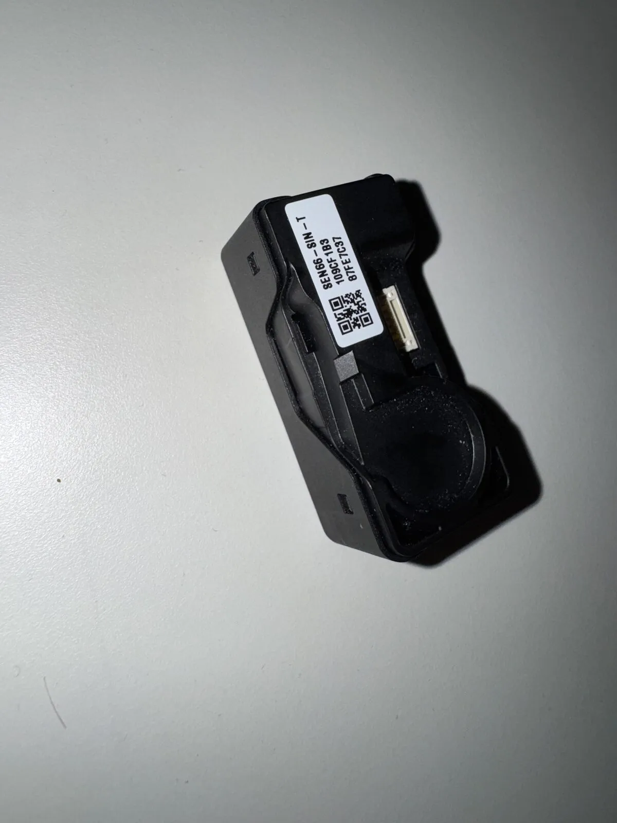
The drawing also revealed something I would never have guessed: on the SEN66 the air inlet and the fan outlet both sit on the same large top face. That single fact determined the entire architecture — the lid needed a large window above the sensor, and the sensor had to sit flush right underneath it.
Step 2: Let It Check Its Own Work
Before a single gram of filament was used, another step went in between: OpenSCAD can render a model to an image from the command line.
openscad -D 'part="body"' --render -o preview.png \
  --imgsize=1600,1000 --camera=0,0,0,58,0,22,0 --viewall model.scad
Claude Code generated those previews and then looked at them itself. That sounds like a gimmick, but it caught real errors: a ventilation slot that accidentally cut through a wall, a cable duct sitting at the wrong height, a lid whose stiffening ribs landed exactly over the sensor’s fan opening. All of that is obvious in a picture and invisible in code.
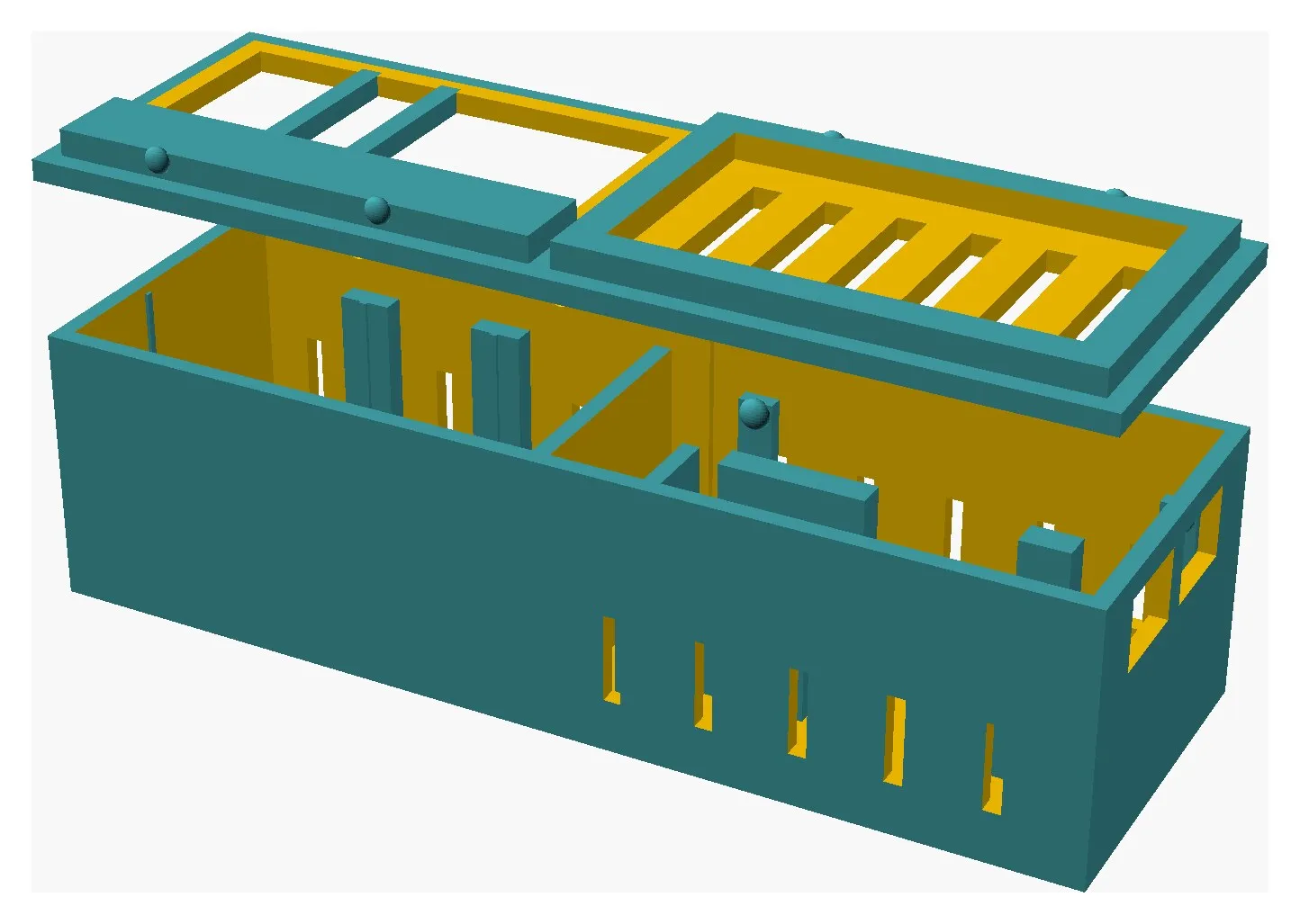
This is the point where the whole thing stops being a text generator and starts being an engineering loop: build, look, correct.
Step 3: Print, Photograph, Patch
And then came the part that no amount of datasheet reading replaces. I printed. And the first print looked like this:
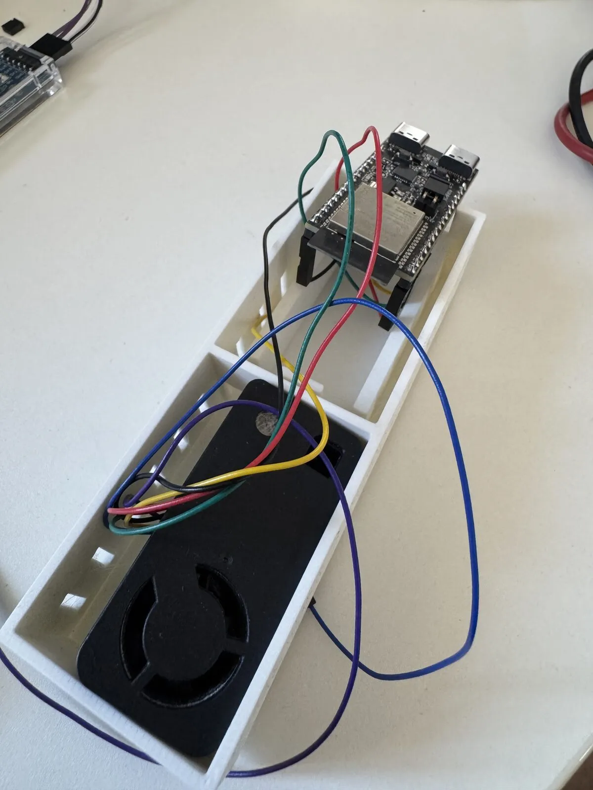
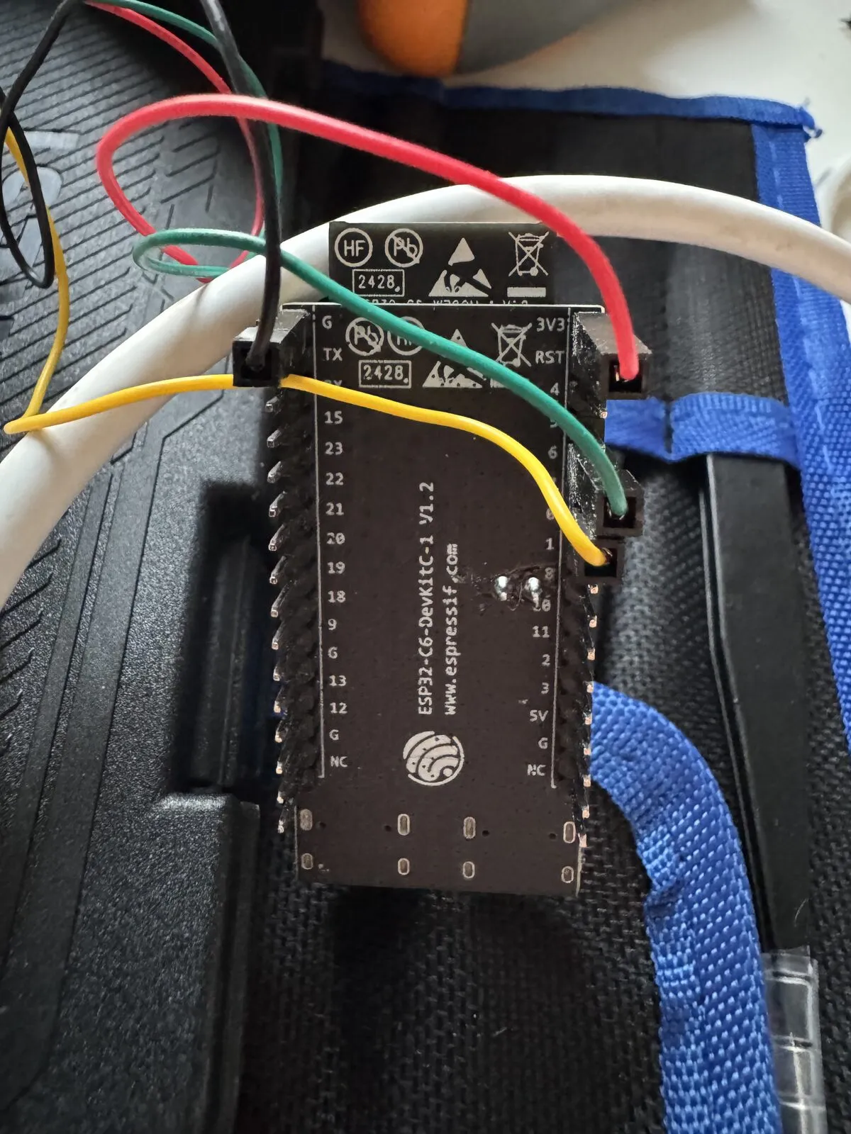
The sensor chamber fit. The board chamber did not — not even close. And the reason is instructive: my jumper wires plug onto pins that stick out from the underside of the board. The model had assumed the connectors sit on top. So it had placed the board 15 mm above the floor to leave room underneath — for connectors that were not there, while the real ones had nowhere to go.
I photographed it and sent the picture. That became the pattern for everything that followed: the photo is the debug channel. I did not describe what was wrong. I showed it. And in almost every photo, Claude Code found something in the model that no drawing had revealed.
Here is the complete, unflattering list:
The connectors were on the wrong side. Assumption: plugged in from above. Reality: hanging below the board. Board height had to be rebuilt twice — first too high, then too low, then right.
The connectors were wider than expected. They sit directly on the pin rows at the board edges — exactly where I had put my support rails. The board has to be carried in the middle, because that is the only place where nothing protrudes underneath.
Two solder pins in the middle of the board. Right in the spot where the new center support was supposed to go. I had seen them in the layout drawing but placed them wrongly. It took a close-up photo of the board’s underside and a pointed question from me before the support was split into four pads with a gap in between.
The sensor is waisted, not notched. The datasheet drawing shows four features on the SEN66’s side faces. I read them as recesses to snap into. Wrong — the housing is simply narrower there. My carefully designed retaining bumps grabbed thin air. I only realized this because I said the sentence “at that spot the housing is narrower and the bumps do not touch”. The fix: no snaps at all on the sides, but thin crush ribs plus a lid that holds the module down from above.
The USB opening was wider than the board. This was my favorite mistake, because the geometry was flawless and the function was nonsense: a single 26 mm wide opening for both USB-C ports. The board is 25.4 mm wide. So when you pulled the cable, the board slid straight out through its own opening.
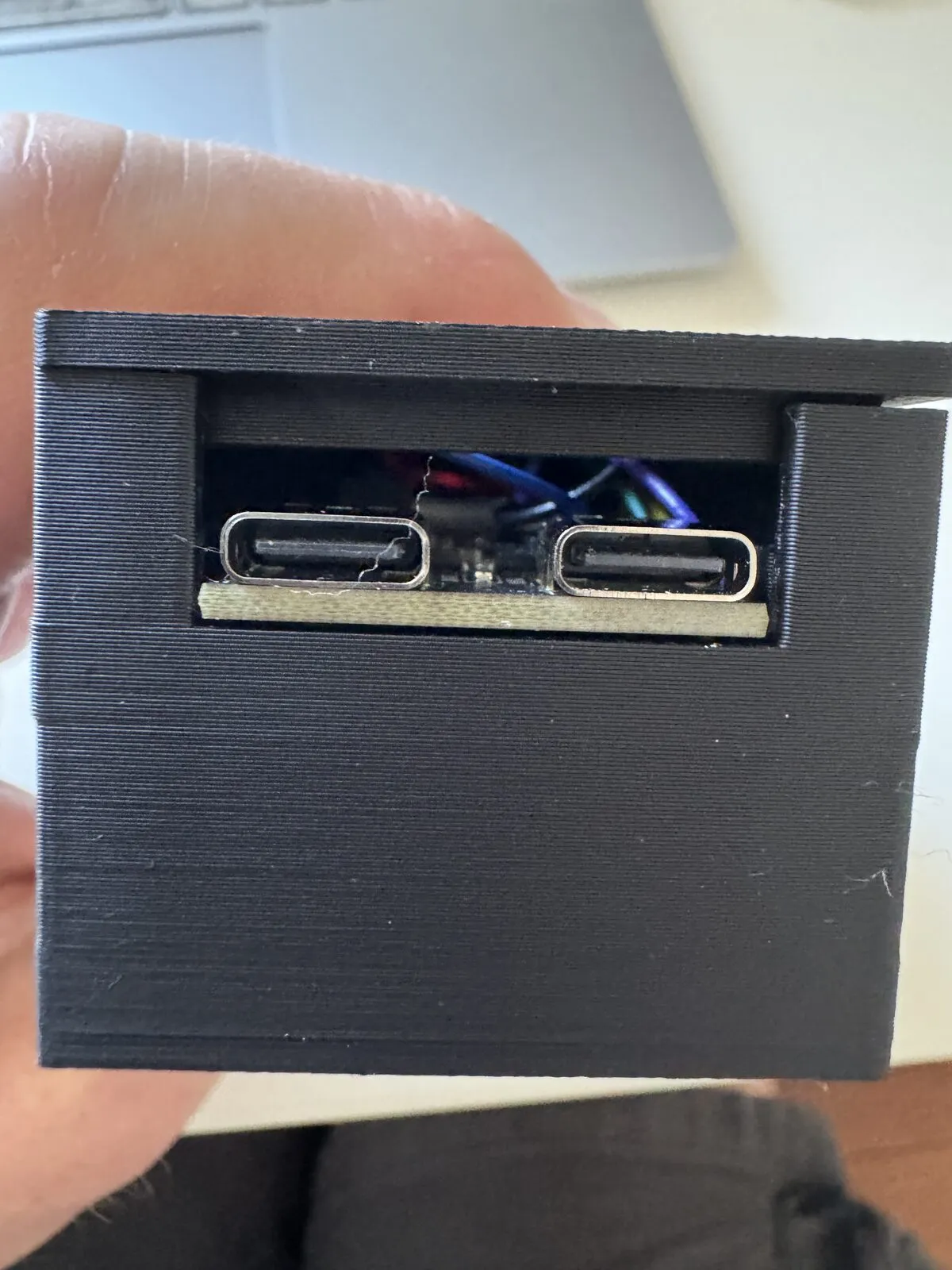
The solution was two separate 11 mm windows with a 3 mm strut between them. The board edge now hits that strut and stays inside. The plugs still fit through, the board no longer does.
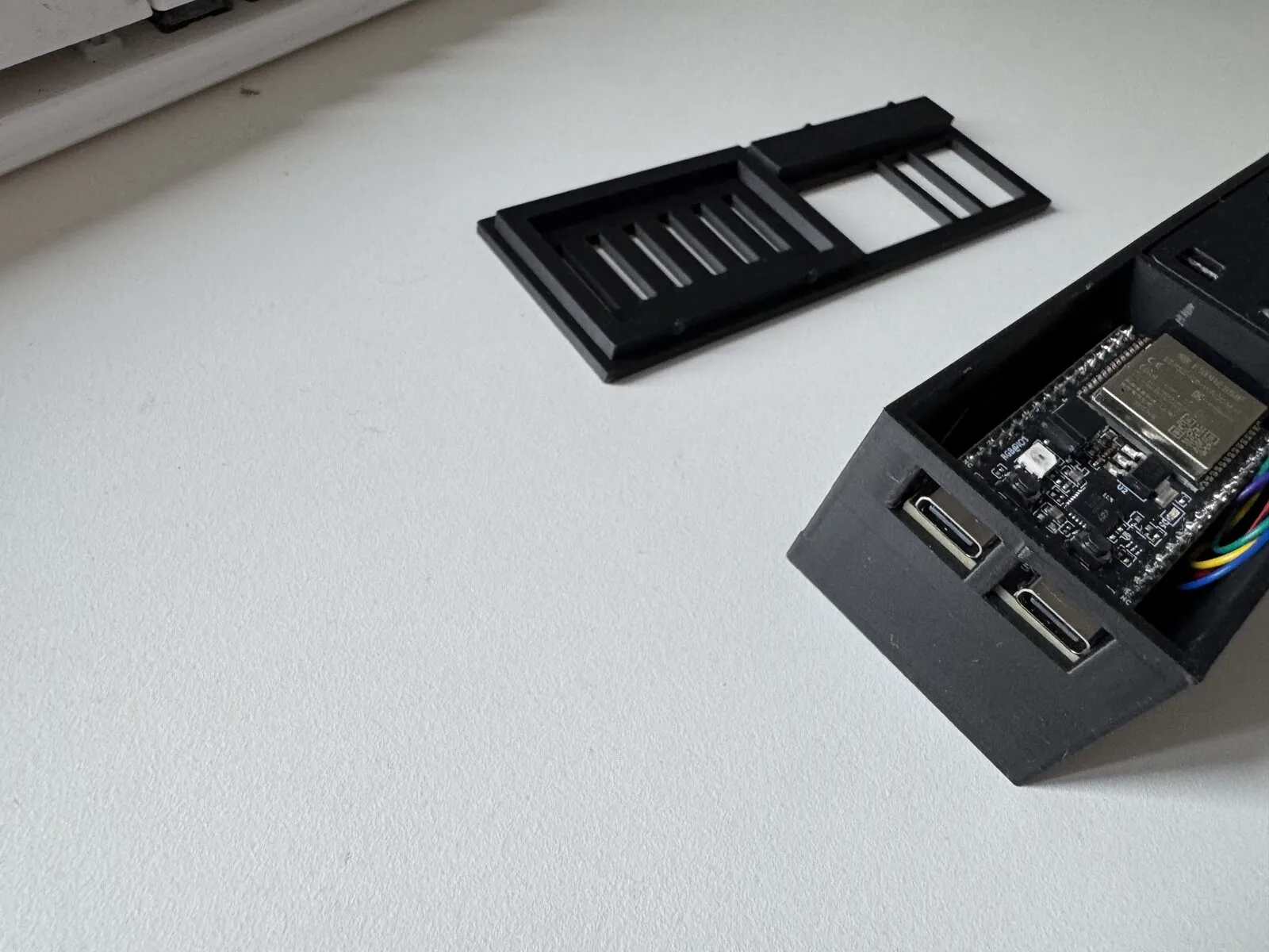
The lid closed too easily. It only held by friction and did not always click. Three parameters fixed it: bigger retaining bumps, deeper engagement, tighter lip fit.
The pattern behind all of this is always the same. Datasheets describe geometry, not installation. How a component is actually wired, which way the connectors face, what protrudes and where — a person holding the part sees it in two seconds, and the drawing does not say a word about it.
The Result
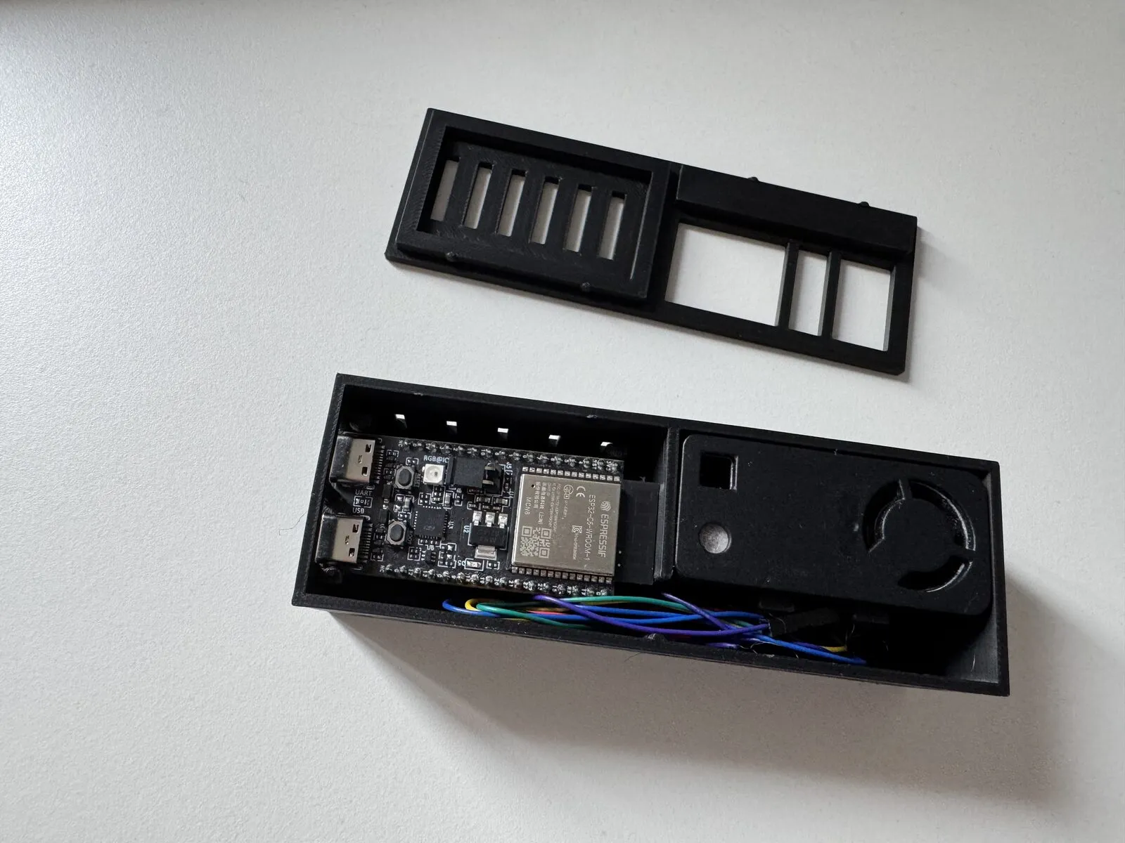
The final enclosure measures 119 × 40 × 32 mm and needs not a single screw:
- Two chambers. Sensor on the left, board on the right, a divider wall in between that keeps the electronics’ waste heat away from the temperature sensor. That matters: the SEN66 reads several degrees too warm if it sits next to a heat source.
- The board clips in. Four posts with retaining bumps grip over the board edge from above, two rails carry it from below in the middle where nothing protrudes.
- Two USB windows with a pull-out stop. Cable in, cable out, board stays put.
- The lid snaps on. Four ball-shaped bumps click into shallow dimples in the walls. Ball shapes are the trick here, because they are self-centering and — unlike classic snap hooks — do not break along the print layers.
- Everything visible stays visible. The status LED shines through a grille, the boot button remains reachable, and the sensor breathes through a large window in the lid.
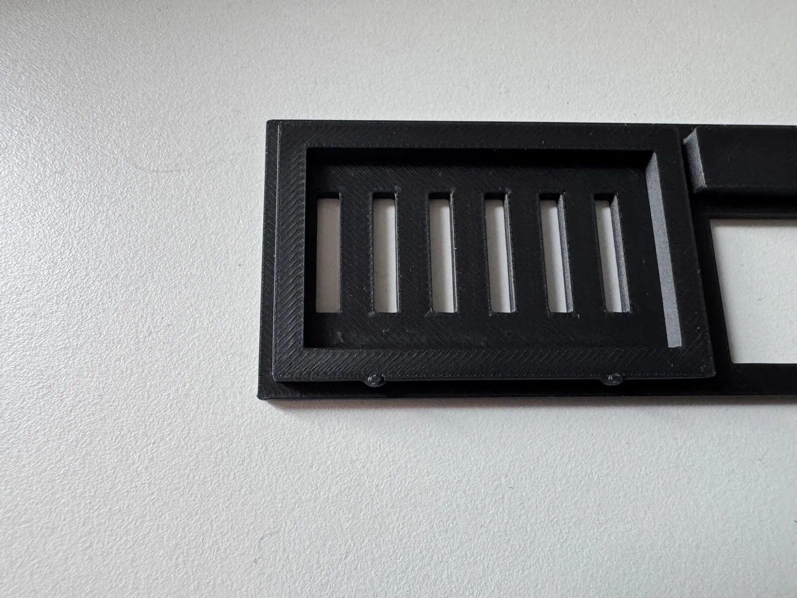
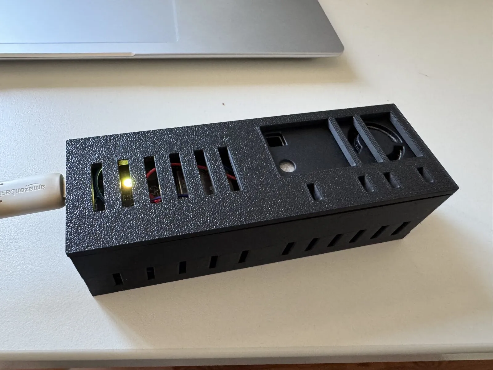
Seven revisions of the model — but only three actual prints. That ratio is the real result. The renders and the photos caught the errors before they cost filament.
The Recipe
If you want to try this, five rules cover most of it:
Choose text-based CAD. OpenSCAD, not Fusion. The model has to be able to read and change what it built.
No guessed dimensions. Insist on the official datasheet or layout drawing, and have every value carry a source comment. Anything that cannot be sourced from a document gets measured with calipers — by you.
Render before printing. Have images generated and have the model look at them. Costs seconds, saves hours.
Photograph instead of describing. “It doesn’t fit” produces guesses. A photo produces a diagnosis. This is by far the strongest lever in the entire process.
One change per print. If you change three things at once and it still does not fit, you have learned nothing.
And a sixth rule that only becomes clear in hindsight: keep asking. Half the errors above were found not by the model but by my own questions — “does the board still fit if the strut is there?”, “how does the lid hold if it sits flush?”. Every single one of those questions uncovered a genuine flaw. This is exactly the pattern I described in AI Writes Faster Than Your Shadow: the machine produces at speed, the human guards the outcome. With physical parts that role is brutally obvious, because there is no room for interpretation. It fits or it does not.
Where This Does Not Work
To be fair about the limits. This approach is strong for technical, boxy geometry with known dimensions: enclosures, brackets, mounts, adapters, spacers. It is weak or useless for organic shapes and free-form surfaces, anything ergonomic that has to feel right in the hand, parts without any documentation, and real assembly kinematics like gears or hinges under load.
And it does not work at all without a printer and without patience. The feedback loop needs the physical part. Anyone hoping for a finished STL from a single prompt will be disappointed — and would probably not want to install the result in their apartment.
Files
The enclosure fits an ESP32-C6-DevKitC-1 together with a Sensirion SEN66 (or any other SEN6x — they share the same form factor):
- OpenSCAD source — all dimensions parametric at the top of the file, with source comments
- Body STL and lid STL
All three prints were done in PLA at 0.2 mm layer height, no supports needed — the snap fit works fine in PLA. If the snap fit ends up too tight or too loose on your printer, snap_depth and pcb_snap_depth in the SCAD file are the two values to adjust.
The sensor itself, by the way, runs on ESPHome and reports into Home Assistant — including a CO₂ traffic light on the board’s onboard LED, which turns yellow above 800 ppm and red above 1400 ppm. But that is a topic for another post.
Written by Dominic Böttger
← Back to blog





Comments are powered by GitHub Discussions. A GitHub account is required to comment.